Vous êtes ici : Accueil > Publications > Chicago Pile(s) > The Monte Carlo model of CP-1

The Monte Carlo model of CP-1

​​​​​The main source of information regarding the development and operation of CP-1 is a 47-page report written by Enrico Fermi himself in 1943 (CP-413), a few weeks after the first divergence of December 1942. This report was classified, then published in open form in 1952, 10 years after the divergence of CP-1 (AECD-3269, 1952; see also: E. Fermi, Am. J. Phys. 20, 536-558, 1952).

Officially, no photos were taken of the fully built pile, with all of the 57 uranium/graphite lattice ​layers in place, but some photos taken during the intermediate steps construction have survived, as well as a few drawings with radial and axial cuts of CP-1. Some later testimonies of the eye-witnesses are also available, but it is to be stressed that most of these documents show slight or severe inconsistencies among them.

​Based on the existing materials, and under reasonable hypotheses where no data were available and/or where existing data were incomplete or inconsitent, we have built a fully detailed three-dimensional model of CP-1 for the Monte Carlo code TRIPOLI-4.

layer32.jpg
Drawing of the layer 32 of the uranium/graphite lattice, from reference E. Fermi, Report CP-413 (1943). Declassified in 1951 (AECD-3269, 1952). See also: E. Fermi, Am. J. Phys. 20, 536-558 (1952).

layer19.jpg
Photo of the layer 10 of the uranium/graphite lattice. Courtesy of ANL.​​
Publié le 22 novembre 2023

Modeling the fuel cells

The uranium/graphite lattice of CP-1 consisted for the most part of alternating layers of uranium-bearing graphite and dead graphite, respecting a cubical lattice with cell side of 8.25 inches. In total, about 44000 bricks were cut, and about 22000 holes were drilled in order to accommodate the fuel lumps. As a stepping stone towards the full three-dimensional model of CP-1, we have first addressed the geometry and material composition of the fuel cells. As reported in CP-413, several combinations of fuel lumps and graphite were chosen for the pile, mainly due to lack of very pure materials: black and brown UO2 and U3O8 cylinders, black and brown UO2 and U3O8 "pseudo-spheres" especially designed to obtain an ideal (almost spherical) fuel lump shape, and finally metal uranium cylinders. The graphite itself came with different qualities, each corresponding to different densities and impurities contents (mainly boron).

combo.jpg

Table listing the various combinations of fuel lumps used in CP-1, from reference E. Fermi, Report CP-413 (1943).

graph.jpg

Table listing the various brands of graphite used in CP-1, from reference E. Fermi, Report CP-413 (1943).

For each combination of fuel and moderator, we have created a database of fuel cells and tested the corresponding nuclear parameters for an infinite lattice: infinite reproduction factor, kinetics parameters and Fermi's four factors.

1brick.bmp

The TRIPOLI-4 model of a graphite brick containing two brown oxide pseudospheres.

brick_agot_metal.png

The TRIPOLI-4 model of a graphite brick containing two metal uranium cylinders.

brick_us_black.png

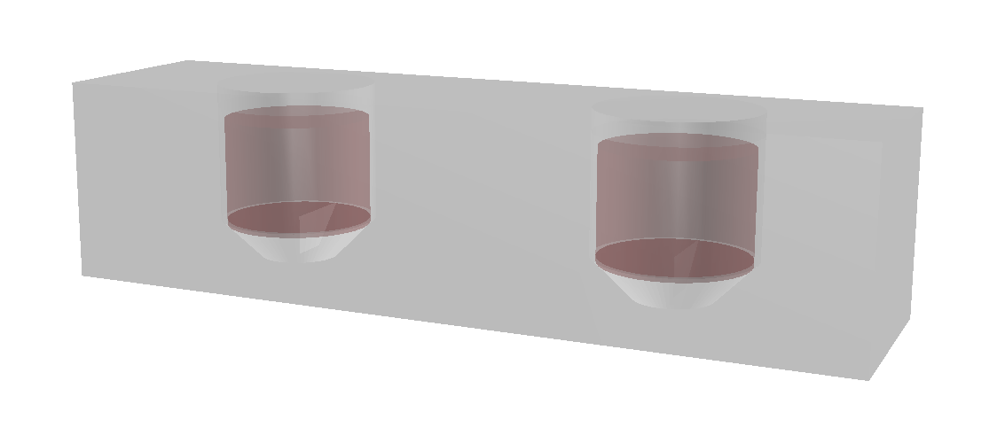
The TRIPOLI-4 model of a graphite brick containing two black oxide cylinders.

lattice.bmp

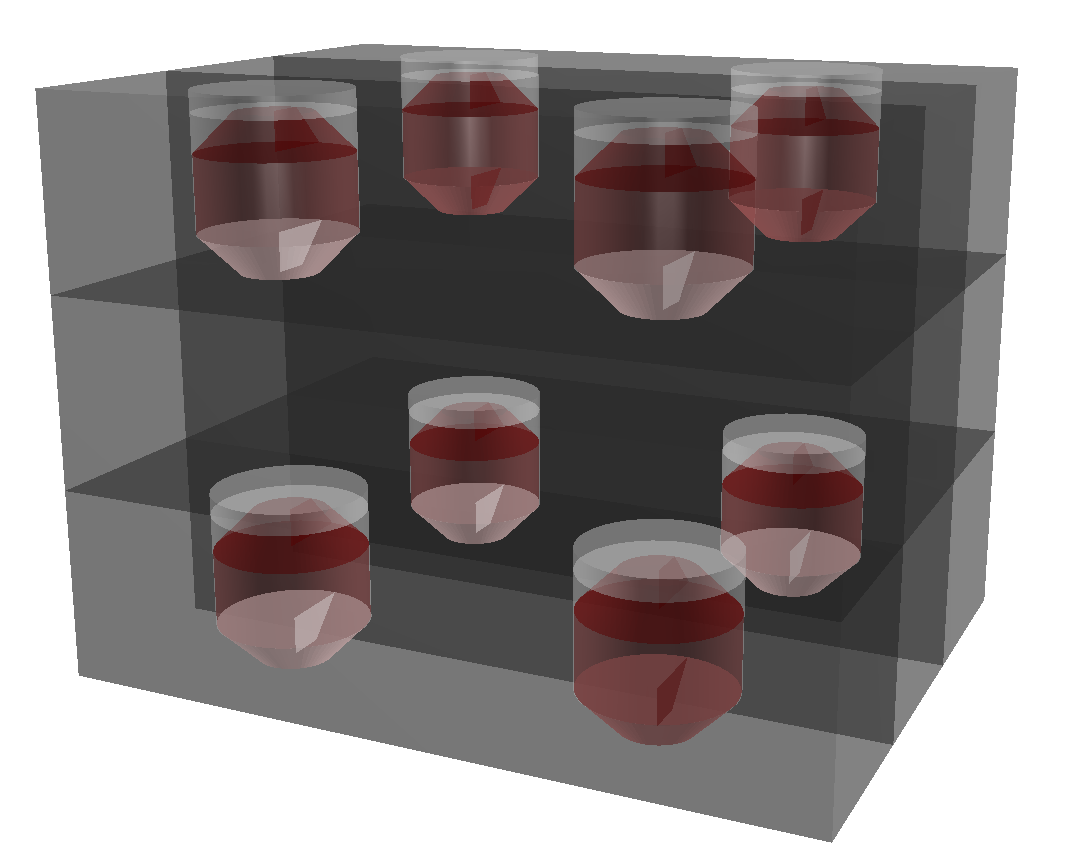
The TRIPOLI-4 model of a lattice portion with four graphite bricks, each containing​ two​ pseudospheres.


Testing the lattice properties

In order to minimize the number of degrees of freedom of the model due to the technological uncertainties (lacking or incomplete data), we decided to adjust the boron content in the graphite of the fuel cells (the main contributor to the impurities detected by Fermi's group) so to fit the infinite reproduction factors inferred in the report CP-413. This procedure is carried out automatically by TRIPOLI-4 thanks to a critical boron search algorithm, capable of finding the boron content that makes the reproduction factor equal to a target value. Most of the reproduction factors listed in CP-413 were estimated up to 1000 pcm uncertainty.

The properties of the various lattices resulting from the possible combinations of fuel lumps and graphite bricks have been computed and compared to those available in the original reports. Some of the most relevant findings are reported hereafter.

lattice_test.jpg

Testing the infinite mutliplication factor and the Fermi's four factors for different combinations of fuel lumps and graphite (shapes and material properties).

area.bmp

Evolution of the migration length as a function of the lattice size.


The full model of CP-1

Once the database of the elementary bricks constituting CP-1 has been developed, it was necessary to establish a "construction plan" in order to place each brick in the pile and establish a full  three-dimensional model. Since a full plan of CP-1 is lacking, to the best of our knowledge, the approach that we have adopted was based on an iterative procedure. First, using the available plans (radial and axial cuts) of CP-1, and assuming certain symmetries, we have built a tentative stack of bricks corresponding to overall shape of CP-1.
planh.png
Drawing of the vertical plan of CP-1, from reference E. Fermi, Report CP-413 (1943).​

Then, we have used mass balance (in terms of number of fuel lumps, total fuel weight and total graphite weight) as given in report CP-413, and further pieces of information stemming from the available photos, in order to achieve a fully detailed model progressively closer to the available technological data, making allowance for uncertainties in geometry and/or material compositions along the way. For the sake of convenience, the generation of the stack of bricks was automatized using a Python script.

mass.jpg
Analysis of the mass balance of the Monte Carlo model, based on the number of fuel elements.

CP1_horizontal_section_safety_rods.png
The TRIPOLI-4 model of layer 32 of CP-1, displaying the safety rod slots, the inner metal core, the outer oxide core (with two kinds of graphite), the wood filler and the wood casing.

The full TRIPOLI-4 model of CP-1 includes a detailed description of each of the 57 layers, encompassing the slots for the safey and control rods, the graphite "pier" that supports the portion of CP-1 where the rods were inserted, the wood casing and the wood filler that supports the lower half of the pile.​

CP1_vertical_section_EW_control_rods.png
The TRIPOLI-4 model of CP-1: vertical section displaying the inner metal core, the outer oxide core (with two kinds of graphite), the graphite pier (on the left) the wood filler (on the right) and the wood casing. The pile lies on a concrete block. The slots of the control rod and of the safety rods are also visible.